


How to Measure a Clear Span Tent: The Ultimate Professional Guide!
 Nov 28, 2025|
 View:1963
Planning an outdoor event, warehouse expansion, or temporary structure project requires precision, and one of the most critical steps is understanding how to measure a clearspan tent accurately. Whether organizing a wedding reception, corporate gathering, sports facility, or industrial storage solution, proper measurement ensures the tent fits perfectly, maximizes usable space, and meets all safety requirements. This comprehensive guide walks through every aspect of clear span tent measurement, from initial site assessment to final verification, equipping readers with the knowledge to make informed decisions and avoid costly installation errors.
Key Takeaways
- Clear span tents require precise measurements of width, length, eave height, ridge height, and site clearance zones
- Site assessment must include ground conditions, slope analysis, overhead clearances, and utility locations
- Proper measurement accounts for anchoring systems, guy ropes, and access pathways requiring 3-10 feet of perimeter clearance
- Interior space planning depends on understanding the difference between total footprint and usable square footage
- Different event types require specific square footage per person calculations for optimal comfort
- Professional measurement tools and techniques ensure accuracy and compliance with local building codes
- Environmental factors including wind exposure, drainage, and seasonal considerations affect measurement requirements
Understanding Clear Span Tent Structure and Dimensions
What Makes a Clear Span Tent Unique
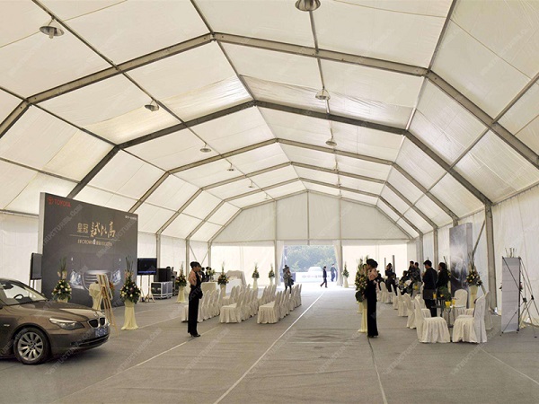
A clearspan tent, also known as a clear span tent or frame tent, distinguishes itself through its engineering design that eliminates interior support poles. This architectural feature creates completely unobstructed interior space, allowing for flexible layout configurations and maximizing usable square footage. The structural integrity comes from an aluminum or steel frame system that supports the entire load through perimeter legs and roof trusses.
Understanding this structural principle is essential for accurate measurement because it affects how space is calculated and utilized. Unlike traditional pole tents that sacrifice 15-20% of interior space to center poles and guy lines, a clear span tent's full footprint translates to functional area.
The Four Primary Dimensions
Every clear span tent measurement begins with four fundamental dimensions:
Width Measurement: The span between the two main support legs running perpendicular to the tent's length. This dimension is typically standardized in the industry, with common widths including 10 meters (33 feet), 15 meters (49 feet), 20 meters (66 feet), 25 meters (82 feet), 30 meters (98 feet), 40 meters (131 feet), and 50 meters (164 feet). The width is fixed based on the structural frame system and cannot be adjusted during installation.
Length Measurement: The distance running parallel to the ridge line from one gable end to the opposite end. Unlike width, length is modular and expandable. Clear span tents typically extend in 3-meter (10 feet) or 5-meter (16 feet) increments, allowing customization to fit specific site dimensions. A tent can be 15 meters wide by 30 meters long, or extended to 15 meters by 60 meters by adding additional frame sections.
Eave Height: The vertical distance measured from ground level to the point where the tent's vertical sidewall meets the sloped roof section. Eave height directly impacts interior clearance, ventilation, and the overall aesthetic presence of the structure. Standard eave heights range from 2.5 meters (8 feet) for smaller residential applications to 4 meters (13 feet) or higher for commercial and industrial uses. Taller eave heights accommodate stacked seating, large equipment, or vehicles.
Ridge Height: The maximum vertical measurement from ground level to the peak of the tent's roof. Ridge height determines the absolute highest clearance point inside the tent and affects the structure's visual profile from exterior viewpoints. This dimension is calculated based on the tent's width and roof pitch angle, typically ranging from 18 to 22 degrees for standard clear span designs.
Understanding the Relationship Between Dimensions
These four measurements are interconnected through geometric relationships. For a clear span tent with a 20-degree roof pitch and 3-meter eave height:
| Tent Width | Eave Height | Approximate Ridge Height | Total Height Gain |
10m (33 ft) | 3m (10 ft) | 4.8m (16 ft) | 1.8m (6 ft) |
15m (49 ft) | 3m (10 ft) | 5.7m (19 ft) | 2.7m (9 ft) |
20m (66 ft) | 3m (10 ft) | 6.6m (22 ft) | 3.6m (12 ft) |
25m (82 ft) | 3m (10 ft) | 7.5m (25 ft) | 4.5m (15 ft) |
30m (98 ft) | 3m (10 ft) | 8.4m (28 ft) | 5.4m (18 ft) |
This relationship means that wider tents naturally have higher ridge heights, which impacts both the internal sense of space and external visual presence.
Comprehensive Site Assessment and Measurement
Step 1: Initial Site Survey and Documentation
Before any measurements are taken, conduct a thorough visual assessment of the proposed installation area. Walk the entire perimeter, noting features that might impact tent placement:
Existing structures: Buildings, walls, fences, and permanent fixtures establish boundaries and may create shade or wind protection. Measure and document the distance from the proposed tent location to each structure.
Landscape features: Trees, gardens, water features, and decorative elements may need protection or could limit placement options. Identify root systems that extend underground, as these affect anchoring capabilities.
Utilities and infrastructure: Locate above-ground and underground utilities including electrical lines, water pipes, gas lines, irrigation systems, and telecommunications cables. Contact local utility companies for professional marking of buried lines before any ground penetration for stakes or anchors.
Access points: Identify vehicle access routes for delivery trucks, forklifts, and installation equipment. Measure gateway widths, overhead clearances, and turning radiuses to ensure frame sections and fabric rolls can reach the installation site.
Create a rough sketch during this initial survey, marking the location of all features. This preliminary documentation guides the detailed measurement process.
Step 2: Measuring the Available Footprint
With the site surveyed, begin precise measurement of the area where the tent will be installed:
Establish corner reference points: Using stakes, flags, or spray paint, mark the four corners of the maximum available rectangular area. These points serve as the reference for all subsequent measurements.
Measure length and width: Using a long measuring tape (100 feet or longer), laser distance measurer, or measuring wheel, record the distance between opposite corners. Measure both diagonals as well—if the diagonals are equal, the area is a true rectangle. Diagonal measurement differences indicate the site is not perfectly square, which may require adjustment during tent installation.
Document with precision: Record all measurements to the nearest inch (or centimeter). While a few inches of variance can be accommodated during installation, larger discrepancies affect tent selection and placement.
Create a scaled diagram: Transfer field measurements to a scaled site plan, either hand-drawn on graph paper or created using design software. Include dimensions on all sides and mark the orientation relative to north for reference.
Step 3: Calculating Required Clearance Zones
The tent's physical footprint is only part of the total space requirement. Clearance zones around the perimeter accommodate anchoring systems, guy ropes, access pathways, and safety buffer areas:
Anchoring system clearance: The type of ground and anchoring method determines clearance needs:
- Grass or soft soil with stakes: 3-4 feet beyond tent legs for standard stake angles (typically 45 degrees)
- Hard surfaces with weight plates: 1-2 feet beyond tent legs for ballast positioning
- Rock or mixed terrain with auger anchors: 2-3 feet for drilling equipment access
- High-wind locations with cable guy systems: 8-10 feet or more for extended stabilization cables
Guy rope zones: While modern clear span tents use minimal guy ropes compared to traditional pole tents, some models still employ perimeter cables for additional stability. Measure and mark zones 5-8 feet from tent corners where guy stakes will be positioned.
Access and circulation: Plan for pathways allowing foot traffic around the tent perimeter. A minimum 3-foot clearance provides basic access; 5-6 feet is preferable for service vehicles, catering carts, or emergency egress.
Safety buffer from hazards: Maintain greater clearance from specific hazards:
- 10 feet minimum from buildings (fire safety codes)
- 15 feet from overhead power lines
- 20 feet from open flames or cooking areas
- Sufficient distance from water features to prevent accidental entry
Add these clearance zones to the tent's actual dimensions to determine the total site area required. For example, a 20m × 30m tent with 5 feet of clearance on all sides needs a site measuring approximately 23m × 33m.
Step 4: Ground Condition and Slope Analysis
The ground's physical characteristics critically impact installation feasibility and measurement requirements:
Surface type identification: Document the ground surface across the entire footprint:
- Natural grass: Most common and easiest for staking; note thickness and root density
- Concrete or asphalt: Requires ballast weights; measure slab thickness and integrity
- Gravel or crushed stone: May use stakes or plates; assess depth and compaction
- Sand or loose soil: Needs specialized anchoring; measure depth to stable substrate
- Pavers or decking: Evaluate weight capacity and attachment options
Slope and grade measurement: Even slight slopes affect installation:
- Measure elevation at each corner: Use a laser level, transit, or smartphone level app to measure ground elevation at each of the four marked corners and at the center point
- Calculate slope percentage: Determine the elevation difference between the highest and lowest points. Divide this difference by the distance between those points, then multiply by 100. For example, a 6-inch drop over 30 feet equals (6/360) × 100 = 1.67% slope
- Assess leveling requirements: Slopes under 2% typically require no adjustment. Slopes of 2-5% can be accommodated with adjustable leg heights on most clear span tents. Slopes exceeding 5% usually require site leveling through grading or platform construction
Drainage assessment: Observe or research water flow patterns during rain. Poor drainage creates standing water under tents, compromising comfort and safety. Measure the location of drainage swales, catch basins, and natural water paths. Avoid placing tents in natural drainage channels or depressions where water accumulates.
Step 5: Overhead Clearance Verification
Vertical space above the tent site is as important as horizontal footprint:
Measure tree canopy clearance: Using a laser distance measurer with angle compensation or traditional surveying techniques, measure the height of overhanging tree branches above the proposed tent location. Maintain a minimum 3-foot clearance between the tent's highest point (ridge) and any branches. Consider additional clearance for wind movement causing branches to sway.
Identify power line proximity: Never install a tent under or near overhead electrical lines. Measure both horizontal and vertical distances to power lines. Consult local electrical codes for minimum separation requirements—typically 15-20 feet horizontal distance and 15 feet vertical clearance for standard residential lines, with greater distances required for high-voltage transmission lines.
Document building overhangs: If the tent will be positioned near buildings with roof overhangs, balconies, or architectural projections, measure clearances carefully. Account for rain gutters that might direct water flow onto the tent and for building features that could damage tent fabric in windy conditions.
Check for flight paths: In rare cases near airports, helipads, or drone operation areas, extreme vertical clearances may be required. Check with local aviation authorities if the site is near an airport or in controlled airspace.
Step 6: Environmental and Seasonal Factors
Comprehensive measurement includes environmental conditions that vary by season and location:
Sun path analysis: Observe or calculate the sun's path across the site at different times of day. This affects placement decisions for events where shade patterns matter. Measure shadow lengths cast by nearby structures and trees during the time of day when the tent will be in use.
Prevailing wind direction: Research or observe typical wind patterns. Position the tent's narrow end (gable) facing prevailing winds when possible to reduce wind load on the structure. In high-wind locations, measure additional clearance for reinforced anchoring systems.
Snow load considerations: In regions with winter use, measure roof pitch and confirm it meets local snow load requirements. Steeper pitches (22+ degrees) shed snow more effectively. Document historical snowfall data for the location.
Temperature extremes: While not a physical measurement, document typical temperature ranges during the intended use period. This informs decisions about sidewall options, HVAC requirements, and material selection.
Determining Required Tent Size for Specific Uses
Calculating Square Footage Per Person
Different event types require varying amounts of space per guest or user. Accurate measurement of needs prevents overcrowding or wasteful excess capacity:
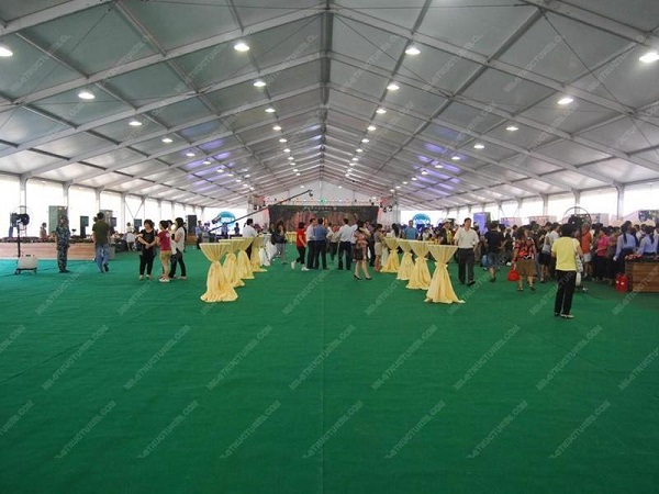
Standing cocktail receptions and networking events: Guests circulate freely with minimal seating. Calculate 6-8 square feet per person for comfortable mingling. For 150 guests: 150 × 7 = 1,050 square feet minimum. This assumes approximately 30% of the space is occupied by bars, food stations, and circulation paths.
Seated dining with round tables: Tables of 8-10 people require more space due to circular table diameter (60-72 inches) plus chair clearance and service aisles. Allocate 10-12 square feet per person. For 150 guests: 150 × 11 = 1,650 square feet. This accommodates table spacing of 5-6 feet center-to-center.
Seated dining with rectangular tables: Long banquet tables (8 feet × 30 inches) are more space-efficient than rounds. Calculate 8-10 square feet per person. For 150 guests: 150 × 9 = 1,350 square feet. This allows for rows of tables with adequate aisle width.
Theater-style seating for presentations: Rows of chairs facing a stage or screen require less space than dining. Use 6-8 square feet per person including aisles. For 200 attendees: 200 × 7 = 1,400 square feet. Add 200-300 square feet for the presentation area, equipment, and staging.
Classroom or conference setup: Tables with seating on one side for note-taking and laptop use require 15-20 square feet per person to accommodate wider table spacing and broader aisles. For 100 participants: 100 × 17 = 1,700 square feet.
Trade show and exhibition space: Booth layouts vary, but standard 10' × 10' booths with aisle access require approximately 150-200 square feet per booth when including aisle space. For 20 booths: 20 × 175 = 3,500 square feet.
Warehouse and storage applications: Measure storage density based on pallet size, racking height, and forklift access requirements. Standard 48" × 40" pallets with 4-foot aisles require approximately 30-35 square feet per pallet position at ground level. Racking systems increase capacity vertically within the tent's height constraints.
Sports and recreational facilities: Activities have specific dimensional requirements. A tennis court requires 36' × 78' playing area plus 12-21 feet of clearance on all sides, totaling approximately 60' × 120' (7,200 square feet). Basketball courts need 50' × 84' plus clearances. Measure sport-specific requirements precisely.
Adding Buffer Space
After calculating base square footage, add 15-20% for practical considerations:
- Service and staging areas: Commercial kitchens, DJ booths, gift tables, registration desks
- Climate control equipment: HVAC units, heaters, fans typically placed inside the tent footprint
- Emergency egress paths: Fire codes may require specific aisle widths and exit routes
- Restroom trailer proximity: If portable restrooms are positioned inside the tent perimeter
- Dance floors or open activity spaces: Often require more space than initial seating calculations suggest
Translating Square Footage to Tent Dimensions
With total required square footage calculated, translate this to tent dimensions:
Example 1: Event requiring 2,000 square feet
- Option A: 20m (66 ft) wide × 10m (33 ft) long = 2,178 sq ft
- Option B: 15m (49 ft) wide × 15m (49 ft) long = 2,401 sq ft
- Option C: 10m (33 ft) wide × 20m (66 ft) long = 2,178 sq ft
Select based on site shape and layout preferences.
Example 2: Warehouse requiring 6,000 square feet
- Option A: 25m (82 ft) wide × 25m (82 ft) long = 6,724 sq ft
- Option B: 20m (66 ft) wide × 30m (98 ft) long = 6,468 sq ft
- Option C: 30m (98 ft) wide × 20m (66 ft) long = 6,468 sq ft
Wider tents provide more column-free span but require more ground clearance and stronger foundations.
Measuring Height Requirements
Determining Necessary Eave Height
Eave height measurement must account for the tallest element that will be positioned against the tent's perimeter walls:
Standard seating events: Minimum 8-foot eave height (2.5 meters) accommodates standing adults comfortably. This is suitable for basic dining or reception events without special equipment.
Events with tall décor or AV equipment: Uplighting, draping, projection screens, and suspended décor require taller eaves. Measure the height of the tallest element and add 2-3 feet minimum clearance. A 10-foot projection screen mounted 2 feet off the ground needs at least 13-foot eaves.
Vehicle storage or drive-through access: Measure vehicle height including roof racks, antennas, or equipment. Add 2 feet clearance minimum. A delivery truck at 12 feet tall requires 14-foot eaves.
Stacked seating or bleachers: Measure the total height of the seating structure including spectators' heads. Add 3-4 feet for comfortable clearance and ventilation.
Industrial equipment and machinery: Measure equipment height including any overhead components, lifted forks on forklifts, or extended reach. Add 3-5 feet operational clearance.
Ridge Height Considerations
Ridge height is calculated based on tent width and roof pitch but affects several practical factors:
Visual proportions: Taller ridge heights create more dramatic interior volume and impressive exterior appearance. For premium events, higher ridges (achieved through wider tents or steeper pitches) enhance ambiance.
Chandelier and ceiling décor clearance: Hanging elements are typically suspended from ridge points or cross beams. Measure from the ground to the bottom of the hanging element, then add 6-8 feet head clearance beneath. A chandelier hanging 8 feet above guest tables needs approximately 14-foot clearance to its mounting point, requiring sufficient ridge height plus structural attachment considerations.
Ventilation and air circulation: Greater vertical volume allows hot air to rise away from occupants, improving comfort. Higher ridge heights benefit tents used in warm weather or with large crowds generating body heat.
Audio and lighting trusses: Technical equipment rigging requires measuring from the ground to the mounting position on the truss. Professional sound systems often need trusses positioned 15-20 feet above ground for optimal coverage.
Professional Measurement Tools and Techniques
Essential Measuring Equipment
Laser distance measurers: Handheld devices project a laser beam to measure distances up to 300-500 feet with accuracy of ±1/16 inch. Models with Pythagorean calculation can measure heights and angles indirectly. Measure from a known reference point to the tent corner locations to establish precise dimensions.
Measuring tapes and wheels: Long measuring tapes (100 feet or more) remain essential for direct linear measurements. Measuring wheels efficiently cover large perimeters—roll the wheel along the ground between points to determine distance. Always verify wheel measurements with tape measurements for critical dimensions.
Digital levels and inclinometers: Electronic levels provide precise slope measurements in degrees or percentages. Smartphone apps using accelerometer sensors can measure slopes, though dedicated instruments offer better accuracy. Measure slope along multiple paths across the site to identify high and low points.
GPS and mapping devices: Professional-grade GPS units record exact coordinates for each corner of the tent site. These coordinates can be imported into CAD software for precise site planning. Consumer smartphone GPS is typically accurate to 15-30 feet, which is insufficient for detailed tent placement but useful for general site location documentation.
Laser levels and transits: These tools project a level line or plane of laser light, allowing multiple measurements referenced to the same elevation datum. Set up the laser level at a central point, then measure the vertical distance from the laser line to the ground at each corner to determine relative elevations.
CAD and design software: Computer-aided design programs allow creation of scaled site plans incorporating all measurements. Software can calculate areas, simulate tent placement options, and identify potential conflicts. Many tent suppliers provide CAD files of their tent models that can be imported into site plans.
Advanced Measurement Techniques
Triangulation for irregular sites: When the installation area is not rectangular, use triangulation to map the space accurately. Measure from a fixed reference point to each corner of the site. Measure the angles between these reference lines using a transit or angle finder. This data allows reconstruction of the exact site shape.
3D laser scanning: For complex sites with multiple elevation changes or extensive obstacles, professional 3D scanning creates a detailed point cloud model of the entire area. While expensive, this technique provides the most comprehensive measurement data for large or challenging installations.
Photogrammetry: Taking photographs from multiple angles and processing them through specialized software can generate 3D site models with accurate measurements. This technique works well for preliminary assessments when site visits are limited.
Special Measurement Scenarios
Multi-Section Clear Span Tent Systems
When connecting multiple clear span tent sections to create larger structures:
Width alignment verification: All connected sections must have identical widths. Measure carefully to ensure frames match exactly. A 20m wide tent cannot connect to a 25m wide tent.
Connection point measurement: Measure the distance between the last leg of one tent section and the first leg of the adjacent section. Standard connections require specific spacing, typically 3-5 meters, to accommodate rain gutter systems.
Rain gutter allowances: Connected tents often include intermediate rain gutters channeling water between sections. These gutters are typically 12-18 inches wide. Measure and account for this additional length when calculating total combined tent length.
Compound configurations: L-shaped, T-shaped, or H-shaped tent layouts require careful measurement of each leg of the configuration. Measure connection angles to ensure they align at true 90-degree intersections (or other specified angles).
Tents on Raised Platforms or Decking
When installing over existing platforms, decks, or constructed flooring:
Platform dimension verification: Measure the platform's exact length and width. Tent legs must be positioned on the platform surface or on support structures capable of bearing the load. If the platform is smaller than the desired tent footprint, extensions or modifications may be necessary.
Weight capacity assessment: Determine the platform's weight-bearing capacity per square foot. Measure the spacing of underlying joists or support beams. Tent leg positions must align with adequately supported areas. A standard tent leg can impose 1,000-3,000 pounds of load depending on tent size and wind conditions.
Edge clearance: Measure the distance from tent leg positions to platform edges. Legs should be positioned at least 2 feet from unsupported edges for safety. If the platform has railings, measure clearances to ensure tent legs and guy ropes don't interfere.
Height above ground: Measure the platform elevation above surrounding ground level. This affects overall ridge height, anchoring options (guy stakes may need to extend beyond the platform to ground level), and stair/ramp requirements for access.
Clear Span Tents in Enclosed Spaces
Occasionally, clear span tents are installed inside existing buildings such as warehouses, arenas, or convention centers to create defined spaces:
Floor-to-ceiling clearance: Measure the exact ceiling height at multiple points across the installation area, as ceilings may not be level. The tent's ridge height must clear the ceiling by at least 2 feet, preferably more. Account for HVAC ducts, light fixtures, and other ceiling-mounted equipment that may reduce clearance.
Column and obstacle mapping: Measure the location of interior building columns, support posts, or equipment that cannot be moved. Create a precise overhead map showing the location of each obstacle relative to the proposed tent position. Tent frames may need to be positioned around these obstructions.
Doorway access for installation: Measure the width and height of building entrances through which tent frames, fabric, and equipment must pass during installation. Tent frame sections are typically 10-16 feet long; ensure doorways can accommodate these dimensions.
Fire suppression system clearance: If the building has automatic sprinkler systems, measure the location and spacing of sprinkler heads. Tent fabric must not block sprinkler coverage patterns. Fire codes typically require maintaining specific clearances between tent peaks and sprinkler heads.
Temporary Foundational Structures
For long-term installations or locations with inadequate ground anchoring, temporary foundations may be constructed:
Foundation footprint measurement: Measure the exact location where each tent leg will be positioned. Concrete pads, ground screws, or ballast plates must align precisely with frame geometry.
Excavation depth requirements: For buried foundations, measure soil depth to stable substrate. Frost depth in cold climates determines minimum foundation depth—measure or research local frost line depth (typically 18-48 inches depending on region).
Leveling verification: After foundation construction, re-measure elevations at each foundation point to ensure they're level within acceptable tolerances (typically ±1/4 inch over the entire tent span).
Creating a Detailed Measurement Report
Documentation Best Practices
Compile all measurements into a comprehensive report for reference during tent selection and installation:
Site plan diagram: Create a scaled overhead view showing:
- Overall site boundaries with dimensions
- Proposed tent outline with exact dimensions
- Distance from tent corners to fixed reference points (buildings, property lines, permanent structures)
- Location of utilities marked with symbols
- Clearance zones illustrated with shaded areas
- North orientation arrow
- Scale notation (e.g., 1 inch = 20 feet)
Elevation profile: For sloped sites, create a side-view profile showing ground elevation changes across the tent footprint. Mark the highest and lowest points with elevation measurements relative to a datum point.
Measurement data table: List all critical measurements in a clear table format:
| Measurement Type | Dimension | Notes |
Available site length | 120 ft | Between property line and existing building |
Available site width | 80 ft | Between driveway and fence line |
Slope percentage | 2.3% | Slopes from north to south |
Distance to nearest building | 15 ft | Garage on east side |
Distance to overhead power line | 25 ft horizontal, 30 ft vertical | On north property line |
Maximum eave height clearance | 12 ft | Limited by overhanging tree branch |
Ground surface type | Natural grass, 4-inch depth | Good soil compaction |
Photograph documentation: Include photographs of the site from multiple angles:
- Overhead view (if possible from drone or elevated position)
- Ground-level view from each corner toward opposite corner
- Close-up photos of ground surface conditions
- Photos showing nearby structures, trees, and obstacles
- Images of utility access points and service areas
Environmental conditions summary: Document weather patterns, seasonal considerations, and site-specific factors:
- Prevailing wind direction (e.g., northwest winds averaging 10-15 mph)
- Sun exposure patterns (e.g., full sun from 11 AM - 4 PM)
- Drainage observations (e.g., gentle slope directs water toward south edge)
- Historical weather data if available
Verification and Quality Control
Before finalizing the measurement report:
Independent verification: Have a second person re-measure critical dimensions, especially tent footprint corners, clearances to obstacles, and elevation differences. Discrepancies indicate measurement errors that should be resolved before proceeding.
Cross-check calculations: Verify that calculated areas, slope percentages, and derived dimensions are mathematically correct. Simple arithmetic errors can lead to significant practical problems.
Confirmation with stakeholders: Review the measurement report with all relevant parties:
- Property owners or venue managers for site approval
- Event planners to confirm space meets requirements
- Tent suppliers to verify dimensions match available tent sizes
- Local building departments if permits require site plans
Update and revision tracking: If measurements are taken far in advance of installation, schedule a verification measurement closer to the installation date. Site conditions can change—trees grow, structures are added, landscaping is modified. Note the measurement date on all documentation and create updated reports if changes are detected.
Common Measurement Errors and How to Avoid Them
Error 1: Underestimating Total Space Requirements
The mistake: Measuring only the tent's physical footprint without accounting for anchoring, clearances, and access routes.
Why it happens: Focus on the tent's interior usable space without considering the full installation footprint. Not understanding that guy ropes, stakes, and ballast extend beyond the tent fabric.
How to avoid: Always add clearance zones to tent dimensions before comparing to available site space. Use the formula: Required site dimension = Tent dimension + (2 × clearance distance). For a 20m wide tent with 1.5m clearance: 20 + (2 × 1.5) = 23m minimum site width.
Real-world impact: A tent is delivered to a site and cannot be installed because stakes would extend onto adjacent property, into landscaping that cannot be disturbed, or too close to buildings for code compliance. This results in installation delays, potential relocation costs, or even event cancellation.
Error 2: Failing to Measure Overhead Clearances
The mistake: Not verifying vertical clearances to tree branches, power lines, or building overhangs until the tent is being erected.
Why it happens: Ground-level measurements are easier and more obvious. Overhead obstacles are easily overlooked, especially when measuring from ground level without looking up thoroughly.
How to avoid: Systematically measure every overhead element. Stand at each proposed tent corner and look upward in all directions. Use a laser distance measurer to quantify heights of any overhead elements. Mark overhead obstacles on the site plan with their height and horizontal position.
Real-world impact: During installation, a tent's ridge or guy rope would contact a tree branch or pass dangerously near a power line. Installation must stop, and the tent is relocated to a different position. This wastes installation time, may result in a suboptimal layout, and can delay event setup. Contact with power lines poses severe electrical hazard risks.
Error 3: Ignoring Ground Slope
The mistake: Assuming ground is level or that slight slopes don't matter for tent installation.
Why it happens: Gradual slopes are difficult to perceive visually. Walking across a 2-3% slope feels relatively flat, but this elevation difference becomes significant across a large tent footprint.
How to avoid: Always measure slope, even when ground appears level. Use a level and measuring tape: place the level spanning 10 feet horizontally, then measure the vertical gap at one end. Divide the vertical measurement by 120 (inches per 10 feet) and multiply by 100 for slope percentage.
Real-world impact: A tent is installed on an unmeasured slope. Water pools at the low end during rain. Furniture and equipment lean or shift. The tent's appearance is compromised—visible sagging or uneven roof lines. In severe cases, unequal leg heights create structural stress on the frame.
Error 4: Confusing Total Footprint with Usable Interior Space
The mistake: Calculating space requirements based on tent footprint dimensions without accounting for interior obstructions and non-usable areas.
Why it happens: Misunderstanding that tent legs, entrance areas, sidewall thickness, and equipment placement reduce functional interior space below the tent's total square footage.
How to avoid: Subtract approximately 5-10% from total square footage to account for interior space losses. For example, a 20m × 30m tent provides 600 sq meters (6,458 sq feet) of total footprint, but only 570-590 sq meters of usable interior space. When calculating guest capacity, use the usable space figure.
Real-world impact: An event feels cramped and overcrowded despite being in a tent that theoretically has adequate square footage. Tables and chairs don't fit in the planned layout. Fire code occupancy limits may be exceeded if calculated on total rather than usable space.
Error 5: Neglecting Seasonal and Environmental Factors
The mistake: Measuring site conditions during one season and installing the tent during another season with significantly different conditions.
Why it happens: Measurements are often taken months before the actual installation. Seasonal changes affect ground conditions, vegetation, sun angles, and weather patterns.
How to avoid: When measuring significantly in advance, note seasonal differences and project how conditions will change. Research typical weather for the installation date. If possible, conduct a verification measurement closer to installation time. Consider worst-case scenarios (heavy rain, high winds, extreme temperatures) in measurement planning.
Real-world impact: Ground measured as firm in summer becomes saturated and unstable during a rainy spring event, compromising anchoring. Trees measured bare in winter have full foliage canopies in summer that reduce clearances. Sun patterns differ dramatically between seasons, creating unexpected glare or inadequate natural lighting.
Error 6: Inaccurate Measurement of Utility Locations
The mistake: Failing to properly locate underground utilities before planning stake positions, or not identifying above-ground utility access points that must remain accessible.
Why it happens: Utilities are hidden underground or not obvious during initial site surveys. Utility marking services are not contacted, or marks fade before installation.
How to avoid: Always contact local utility location services (such as "Call Before You Dig" or equivalent services) at least 3-5 business days before measurement activities. Have utilities marked with paint or flags. Photograph and document the exact location of marks. Measure distances from utility lines to proposed tent corners and stake positions.
Real-world impact: A stake or auger anchor punctures an underground electrical line, water pipe, or fiber optic cable during installation. This creates safety hazards, service disruptions, expensive repair costs, potential legal liability, and significant event delays.
Error 7: Not Accounting for ADA and Accessibility Requirements
The mistake: Measuring only the tent footprint without planning for accessible entrances, pathways, and interior circulation.
Why it happens:
Accessibility requirements are not always top-of-mind during initial measurement. The focus is on fitting the tent on the site rather than ensuring universal access.
How to avoid: Measure and plan for accessible routes from parking areas to tent entrances. Ramps require specific slope ratios (typically 1:12 for permanent installations, sometimes 1:8 for temporary). A 2-foot elevation change requires 24 feet of ramp length. Inside the tent, measure aisle widths to ensure they meet minimum requirements (typically 36 inches for accessible routes).
Real-world impact: The completed installation does not meet legal accessibility requirements, potentially violating ADA regulations. Modifications must be made at the last minute, or individuals with disabilities cannot fully access the event space. This creates legal liability and fails to serve all guests appropriately.
Regulatory Compliance and Permit Requirements
Understanding Local Building Codes
Most jurisdictions require permits for temporary structures above certain size thresholds. Measurement affects permit requirements:
Size thresholds: Research local regulations for permit requirements. Common thresholds include:
- Tents over 200 square feet
- Tents that will be in place for more than 7-14 days
- Tents with sidewalls or completely enclosed
- Tents used for assembly (occupancy over 50 people)
Measure the tent carefully to determine if it exceeds thresholds that trigger permitting.
Setback requirements: Zoning codes specify minimum distances from property lines, buildings, septic systems, and other features. Measure these distances accurately and confirm they meet requirements before submitting permit applications.
Fire safety clearances: Fire codes mandate specific clearances:
- 10-20 feet from buildings (varies by jurisdiction)
- 20 feet from open flames or cooking areas
- Specific separation distances between multiple tents
- Minimum distances from fire hydrants or emergency vehicle access routes
Measure and document compliance with all fire safety clearances.
Occupancy calculations: Fire marshals calculate maximum occupancy based on tent size and use. Measure total square footage and identify exit locations to support occupancy determinations.
Engineering and Structural Certifications
Large or long-term clear span tent installations may require engineering review:
Wind load calculations: Provide accurate measurements of tent dimensions, eave height, and ridge height to engineers calculating wind loads. Local wind speed data (typically from building codes specifying 3-second gust wind speeds with various return periods) combined with tent geometry determines anchoring requirements.
Snow load analysis: In regions with winter use, measure roof pitch and confirm the tent design meets local snow load requirements (typically specified in pounds per square foot based on ground snow loads).
Soil bearing capacity: For large tents, engineers may need to calculate whether soil can support concentrated loads at leg positions. Measure and provide soil type information (clay, sand, loam, rock, etc.) and any known geotechnical data.
Pre-Installation Verification
Final Measurement Check
Even with comprehensive initial measurements, conduct a final verification before installation begins:
Re-measure critical dimensions: Verify that the available space still matches original measurements. Confirm that no changes have occurred since the initial survey—new landscaping, structures, vehicle parking, or other modifications.
Stake out the exact tent position: Using the measurements from the site plan, stake the four corners of the tent footprint with high-visibility marking (flags, spray paint, or stakes with ribbon). Measure diagonals to ensure the layout is square (diagonals should be equal). Physically walk the perimeter to verify clearances.
Confirm with installation crew: Provide the installation team with the complete measurement report and site plan. Review any site-specific considerations, obstacles, or constraints. Answer questions about measurements before equipment arrives.
Weather verification: Check the forecast for installation day. Excessive wind, rain, or extreme temperatures may affect installation and could require schedule adjustments. Wet ground conditions affect vehicle access and anchoring techniques.
Frequently Asked Questions
How accurate do my measurements need to be?
Site footprint measurements should be accurate within 6 inches. Overhead clearances, especially near power lines, require 1-2 inch accuracy for safety. Access point measurements must be precise—underestimating by 3-4 inches can prevent frame sections from passing through.
Can I measure the site myself or need professional help?
Small residential events on level, straightforward sites can be self-measured. Professional surveys are recommended for tents over 40 feet wide, sloped sites, areas near utilities, or installations requiring permits.
What if my measurements don't match standard tent sizes?
Clear span tent lengths are customizable in 3-5 meter increments. Width is fixed (10m, 15m, 20m, etc.), but length adjusts to fit available space. Consider narrower widths with greater length to maintain square footage.
How do I measure irregular sites with obstacles?
Break the area into measurable geometric sections. Establish a reference baseline and measure perpendicular distances to perimeter points. Use triangulation from two fixed points to map obstacles accurately.
What's the minimum clearance from buildings?
Fire codes typically require 10-20 feet between tents and buildings. Even when closer placement is permitted, maintain 10 feet minimum for air circulation, emergency access, and practical installation needs.
How do I measure slope without professional equipment?
Place a 10-foot level horizontally across the slope. Measure the vertical gap at the elevated end. Calculate slope percentage: (elevation change in inches / 120 inches) × 100. A 6-inch rise over 10 feet equals 5% slope.
What measurements are needed for deck installations?
Measure deck dimensions, corner elevations, height above ground, and distances to support posts. Document load capacity—tent legs impose 1,000-3,000 pounds of concentrated load. Verify the deck structure can support these loads.
How far in advance should I measure?
Measure 2-3 months before installation when possible. For earlier measurements (6+ months), conduct verification 2-4 weeks before installation. Always perform visual verification the day before setup.
Measuring a clear span tent site comprehensively and accurately forms the foundation for successful installation, whether for a wedding celebration, corporate event, sports facility, or industrial application. By following the systematic approach outlined in this guide—from initial site assessment through final verification—tent users can ensure optimal fit, compliance with safety requirements, and efficient use of available space. The investment of time in thorough measurement prevents costly errors, installation delays, and compromised event quality.
For those seeking a reliable clearspan tent supplier who provides comprehensive support throughout the measurement, planning, and installation process, Meister tent specializes in high-quality clear span tent solutions with expert technical guidance for projects of all scales.